Continuous cooking cationic and oxidized starch sorts in semi-automated or fully automated modes.
Performancegroups: JC100-JC1000
Performance range: 100to1000kg/hr
Slurry concentration: 6to10% (cationic starch)
Slurry concentration: 25to30% (oxidizedstarch)
Outlet concentration: 1to4% (cationic starch)
Outlet concentration: 10to15% (oxidizedstarch)
Powerinput: 2.2to4kW
Function brief description
Powder starch is dosed by means of precise worm dosing device into a slurry tank where it is mixed with water and slurry is formed. The slurry concentration depends on the starch sort and use. Starch slurry is continuously pumped by means of screw pump into a static mixer where saturated steam is injected into slurry. That is the beginning of the cooking process being underway in a cooking tube following the mixer. The cooking temperature is set by means of control circuit on a preset value depending on the starchsort. The cooking tube is followed by yester static mixer bringing diluting/cooling water into the cooked starch solution
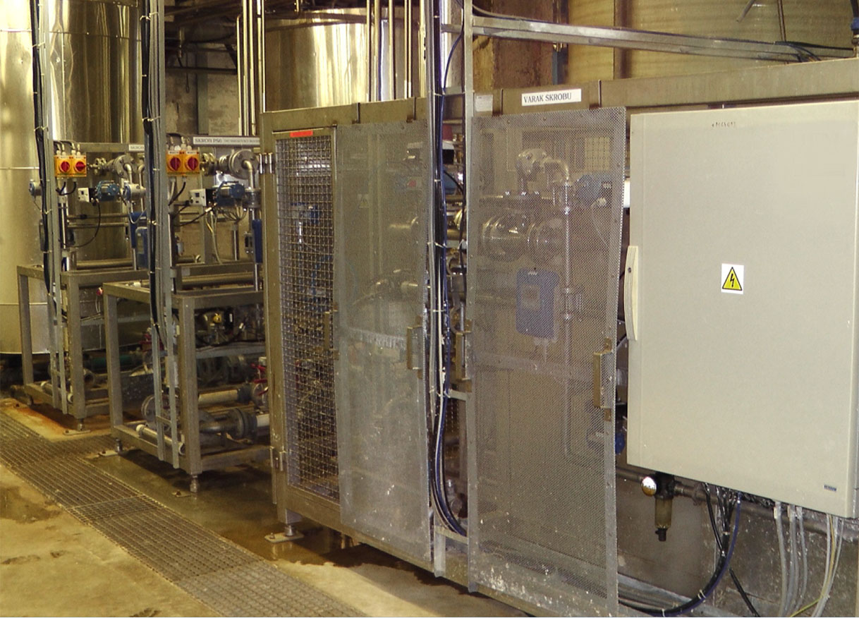
The machinery design and safety comply with the EU and EAC industrial standards.
The outlet concentration is controlled by means of dilution water quantity. Its throughput is controlled by control circuit. Starch diluted onto a required outlet concentration and cooled down to 60 to 85°C enters the storage tank and it is ready for further use. The process is identical for both cationic and oxidized starch.
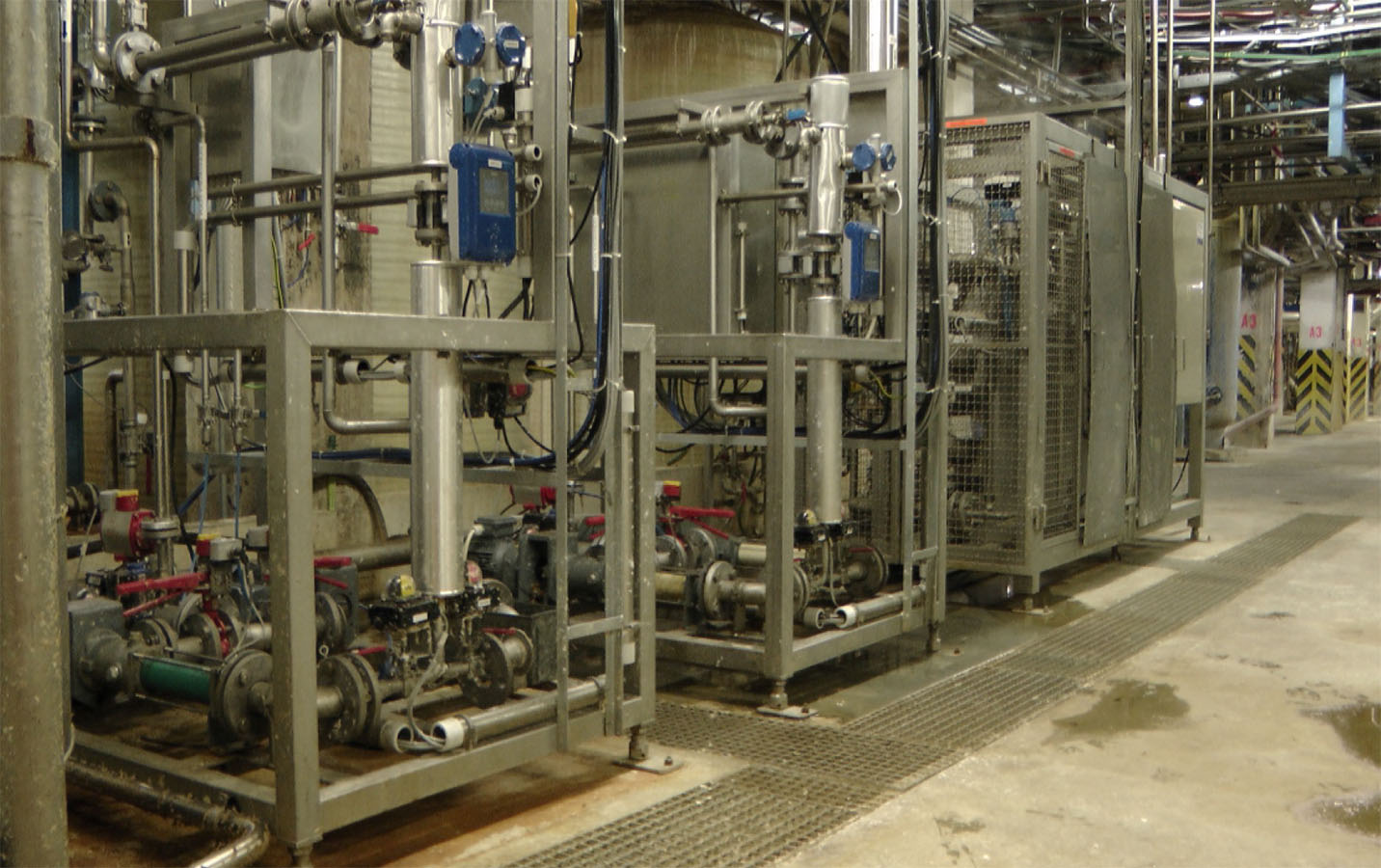
Cooker main parts
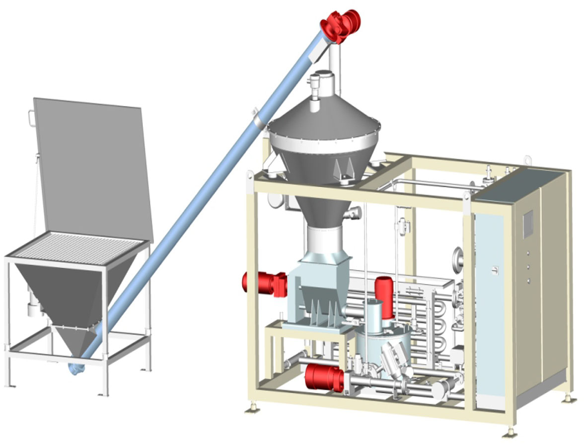
- Powder starch source – a hopper integrated in a support frame or certain type of a lowor high-volume silo for higher starch demand (the silo accessories are designed separately or particular applications)
- Precise worm dosing device with a drive and arms preventing arising cavities
- Slurry tank with a high-performance agitator
- System controlling water throughput into the slurry tank-depends on the cooker type
- Slurry pump with or without performance control-depends on the cooker type
- Slurry filter screening coarse mechanical impurities
- Static mixer for steam injection
- Circuit for automatic cooking temperature control
- Cooking tube
- Static mixer for dilution/cooling water input
- Circuit for an automatic/manual dilution /cooling water throughput control
- Set of measuring & control elements
- Electric switchboard (wherever required)
- Support frame
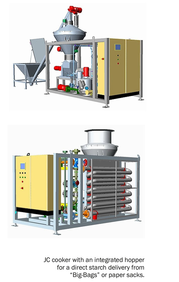
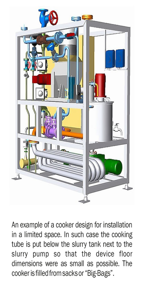
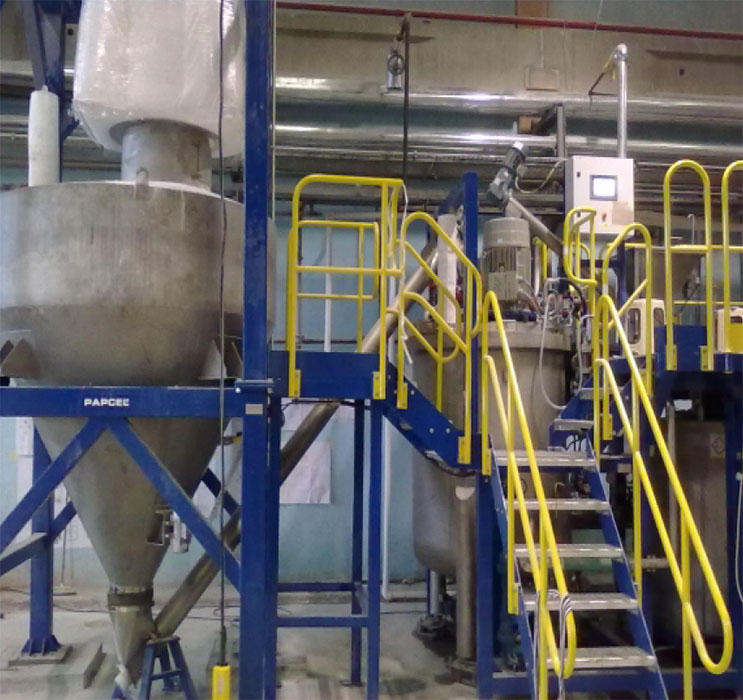
An example of a cooker design for installation in a limited space. In such case the cooking tube is put below the slurry tank next to the slurry pump so that the device floor dimensions were as small as possible. The cooker is filled from sacks or “Big-Bags”.
Cooker concept
K
Compact– slurry unit installed in the frame together with the cooking part
O
separate– slurry unit installed separately from the cooking part
Control system
–
none– – the cooker is controlled by means of an external control system
S
Simatic– the cooker is equipped with a PLC based on Simatic type S7
L
logo– the cooker is equipped with a simple programmable controller
Filling slurry tank with water
A
automatic– water throughput into the slurry tanks is controlled by an automatic control valve
P
float– water throughput into the slurry tank is controlled by a float valve
Slurry throughput control
F
frequency converter– the slurry pump is controlled by a frequency converter the slurry pump without a performance control
– the slurry pump without a performance control
Back pressure control
A
automatic– the cooking tube pressure is controlled by an automatic control valve
M
manual– the cooking tube pressure is controlled by a manual valve
Dilution control
A
automatic– the dilution water flow through the cooking tube is controlled by an automatic control valve
M
manual– the dilution water flow through the cooking tube is controlled by a manual valve
Flushing
P
water for quick flushing is connected to the slurry pump suction side
– flushing cooker enabled by water connected to the slurry tank
Cooker performance control
A
automatic– – the cooker works with a performance proportional control
– the cooker works with a constant performance in an on/off mode
Starch hopper
N
– a starch hopper installed in the support frame is part of the cooker
– no hopper, the starch source is a silo
The JC type cooker with an integrated hopper equipped with a device for easy filling from paper sacks. In this case starch is poured into a small hopper and then delivered by means of worm conveyor to a cooker hopper. The design is advantageous wherever the ceiling height is not sufficient.
Software
The JC cookers are delivered including SW enabling a fully automated cooker operation in predefined steps – sequences. The sequences enable cooking and flushing automated modes at reproducible values before and after finishing the cooking process. The cooker can be switched to a manual mode and the operation can be carried out by means of a control board installed on the switchboard front door. During the cooker operation the cooking process conditions like media parameters, functions and statuses of particular cooker key elements and control circuit statuses are monitored; if any parameter deviates from control range an alarm message is generated and saved in an alarm bank.
The cooker performance is usually controlled depending on the cooked starch storage tank level height either in an on/off mode (the cooker works with a constant performance, starts on the bottom level and stops after reaching the top level) or it works with a variable performance depending on the storage tank level fall speed.
Technical data
Starch sort: cationic or oxidized
Starch origin: potato, corn, wheat, tapioca
Starch source: volume integrated in the cooker support frame 3(volume 100 to 400 dm) medium or large volume silo (volume 5 to 150 m )
Starch packing: paper sacks 25 to 40 kg “Big-Bags” 600 or 1 000 kg road tanker, starch stored in a high-capacity silo
Starch dosing: precise worm dosing device with a drive and arms preventing arising cavities, driven by an electric motor and arms drive final gear
Cooking time: 1 minute for potato and tapioca starch 2 minutes for corn and wheat starch
Heating medium: saturated steam 4 to 5 bar abs
Water: fresh or treated without mechanical impurities,minimum pressure 3.5 bar
Instrument air: dew point -20°C, pressure 5 bar
Performance change speed: dQ = 5 kg/min or a ramp change
Examples of JC cookers process diagrams with various starch filing modes
An example of JC cooker diagram with an integrated hopper, water throughput into the slurry tank controlled by an automatic control valve and an automatic control circuit with an automatic control valve. The cooker is controlled by a Simatic based PLC.
An example of JC cooker diagram filled from a medium silo, water throughput into the slurry tank controlled by an automatic control valve and an automatic control circuit with an automatic control valve. The cooker is controlled by a Simatic based PLC.
An example of JC cooker diagram filled from a large-volume silo, water throughput into the slurry tank controlled by an automatic control valve and an automatic control circuit with an automatic control valve. The slurry part is installed in a separate support frame below the silo output cone and connected to the cooking part by a pipeline. The cooker is controlled by a Simatic based PLC.